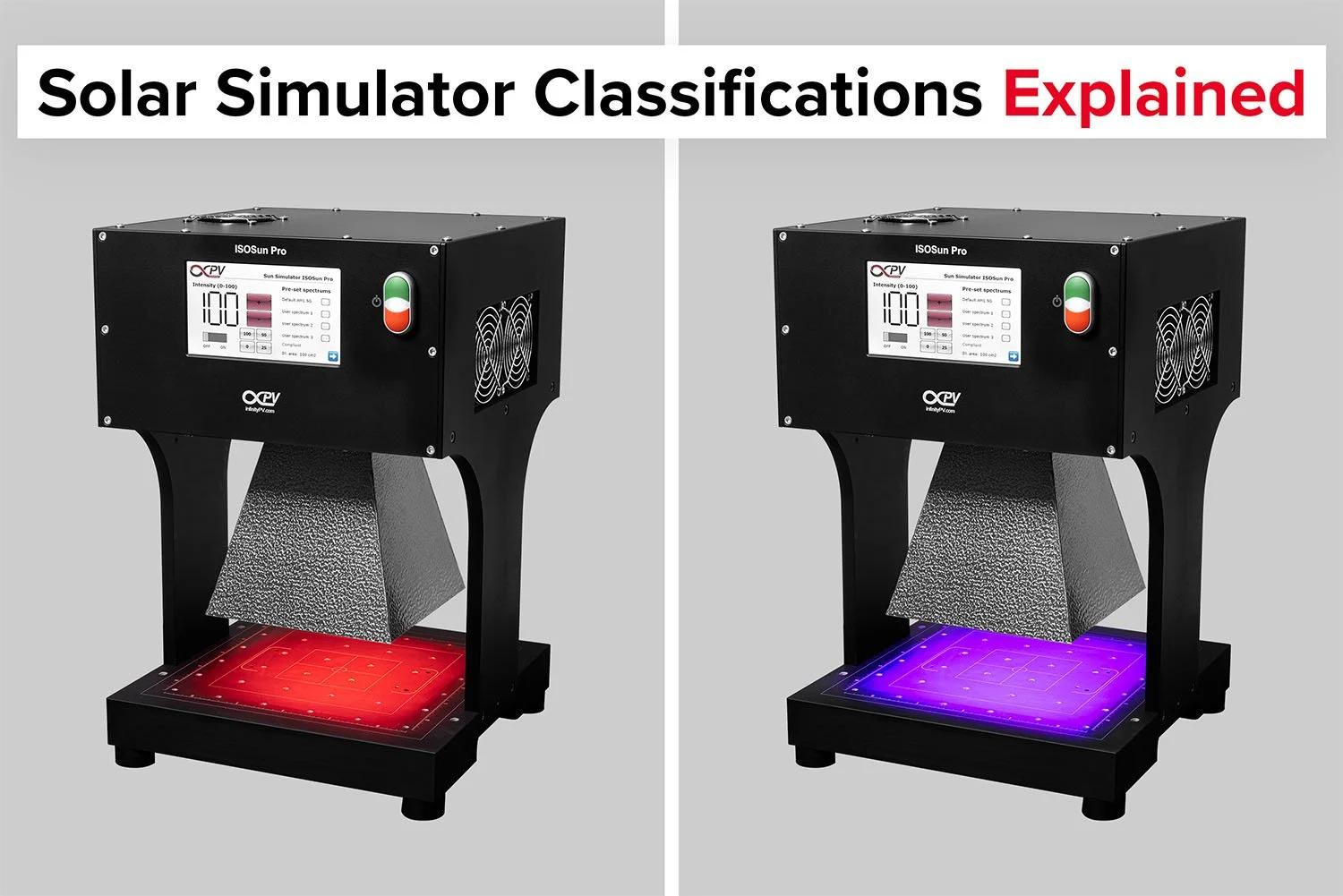
Solar Simulator Classifications Explained: Spectral Match, Uniformity, and Stability
A Solar Simulator is a device that mimics natural sunlight and can be used to among other test and characterize photovoltaic (solar) cells and modules in a controlled laboratory environment. Solar simulators produce a spectrum of light that closely resembles the solar spectrum, and they can provide consistent and repeatable conditions for study and testing various solar cell parameters.
When classifying solar simulators, they are evaluated on
Spectral match: The ratio of the spectral match with the solar spectrum
Spatial Non-uniformity: The deviation in uniformity of the light intensity on the illuminated area
Temporal Instability: The stability of the light intensity over time
Depending on how well the solar simulator perform within each of these areas it is classified they are graded A, B or C. A solar simulator classified as B in Spectral match, C in Uniformity and A in stability would have the final classification of BCA where as a solar simulator meeting the requirements for A in all three categories will be classified as AAA.
| Classification | Spectral Match (all intervals) | Spatial Non-uniformity of irradiance | Temporal Instability of irradiance | Applicable Standards |
|---|---|---|---|---|
| Class A | 0.75–1.25 | 2% | 2% | IEC 60904-9, ASTM E927, JIS C 8912 |
| Class B | 0.6–1.4 | 5% | 5% | IEC 60904-9, ASTM E927, JIS C 8912 |
| Class C | 0.4–2.0 | 10% | 10% | IEC 60904-9, ASTM E927, JIS C 8912 |
In addition to the classical A,B,C classification that covers all wavelengths in the solar spectrum, a new classification A+ was introduced in 2020 focusing only on the wavelengths from 300 nm – 1200 nm which are the most relevant for the exploitation of sunlight for power generation.
| Classification | Spectral Match (from 300 nm–1200 nm) | Spatial Non-uniformity of irradiance | Temporal Instability of irradiance | Applicable Standards |
|---|---|---|---|---|
| Class A+ | 0.875–1.125 | 1% | 1% | IEC 60904-9:2020 |
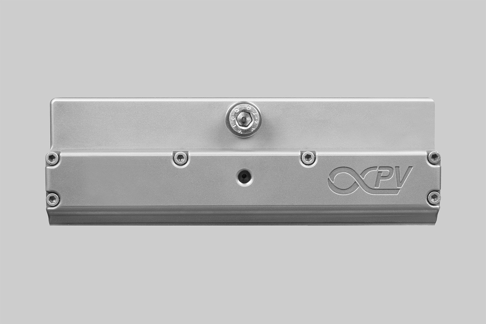
It’s easy to change reflectors on the ISOSun Pro Solar Simulator.
Matching the Solar Spectrum:
Solar simulators aim to replicate the spectral output of sunlight, particularly the “Air Mass 1.5 Global” (AM 1.5G) spectrum, which is used for standard solar cell testing. “AM-x” is a way of describing the solar spectrum under different conditions, where x indicates that the light has passed through x times the air mass of the atmosphere measured perpendicular to the earths surface. As molecules in the atmosphere absorb parts of the light from the sun there is a quite significant difference between the solar spectrum in outer space (AM0) and at the earths surface. AM1.5 was originally chosen as the standard for the solar spectrum as it is a good average representation of the solar spectrum of the most heavily populated areas on earth. The G stands or Global, which means that it includes both direct sunlight and indirect, scattered light from the sky.
Key Criteria and Categories
Key criteria and categories that are used to describe how well a light source matches the AM1.5G spectrum involves:
The light source's output spectrum compared against the AM1.5G reference spectrum. This involves analysing how well the wavelengths and intensities of light produced by the source correspond to the spectral distribution of sunlight.
A good light source should emit light across the visible spectrum with attention to the near-infrared (NIR) and ultraviolet (UV) regions, closely replicating the proportions found in the AM1.5G spectrum.
The intensity of the light source should be calibrated to match the total solar irradiance (approximately 1000 W/m²) at AM1.5G conditions. This is important for ensuring that the energy input during testing is representative of the real sun.
Traditionally, lights sources like xenon, arc, metal halide or tungsten halogen light bulbs combined with optical filters have been used to get the best match with AM1.5G conditions. Following this, the huge evolution within LED light sources has opened new possibilities for matching the light spectrum by tuning the individual wavelengths of the LEDs.
Spatial non-uniformity
Spatial non-uniformity refers to how evenly the light is distributed across the illuminated area of the solar simulator. Ideally, the light intensity should be consistent throughout the test area to ensure accurate and reliable testing of solar cells or modules.
$$ S_{NE} = 100 \times \frac{I_{S,\text{max}} - I_{S,\text{min}}}{I_{S,\text{max}} + I_{S,\text{min}}} $$
Where:
\( I_S \) = Normalized short-circuit current detected by a solar cell through mapping of the active area to be defined
Temporal instability
Temporal instability refers to the stability of the light intensity over time. Fluctuations in light intensity during a test can affect the accuracy and repeatability of results. A stable light source is essential for maintaining consistent testing conditions and obtaining reliable data.
The temporal instability of the light intensity is defined as
$$ T_{IE} = 100 \times \frac{I_{T,\text{max}} - I_{T,\text{min}}}{I_{T,\text{max}} + I_{T,\text{min}}} $$
Where:
\( I_T \) = Circuit current detected by a solar cell during the period of data acquisition
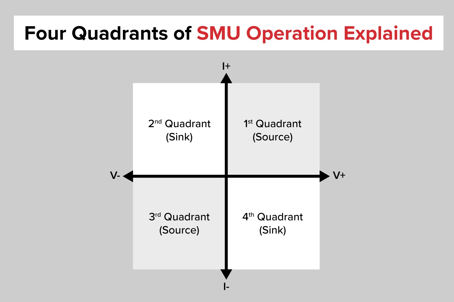
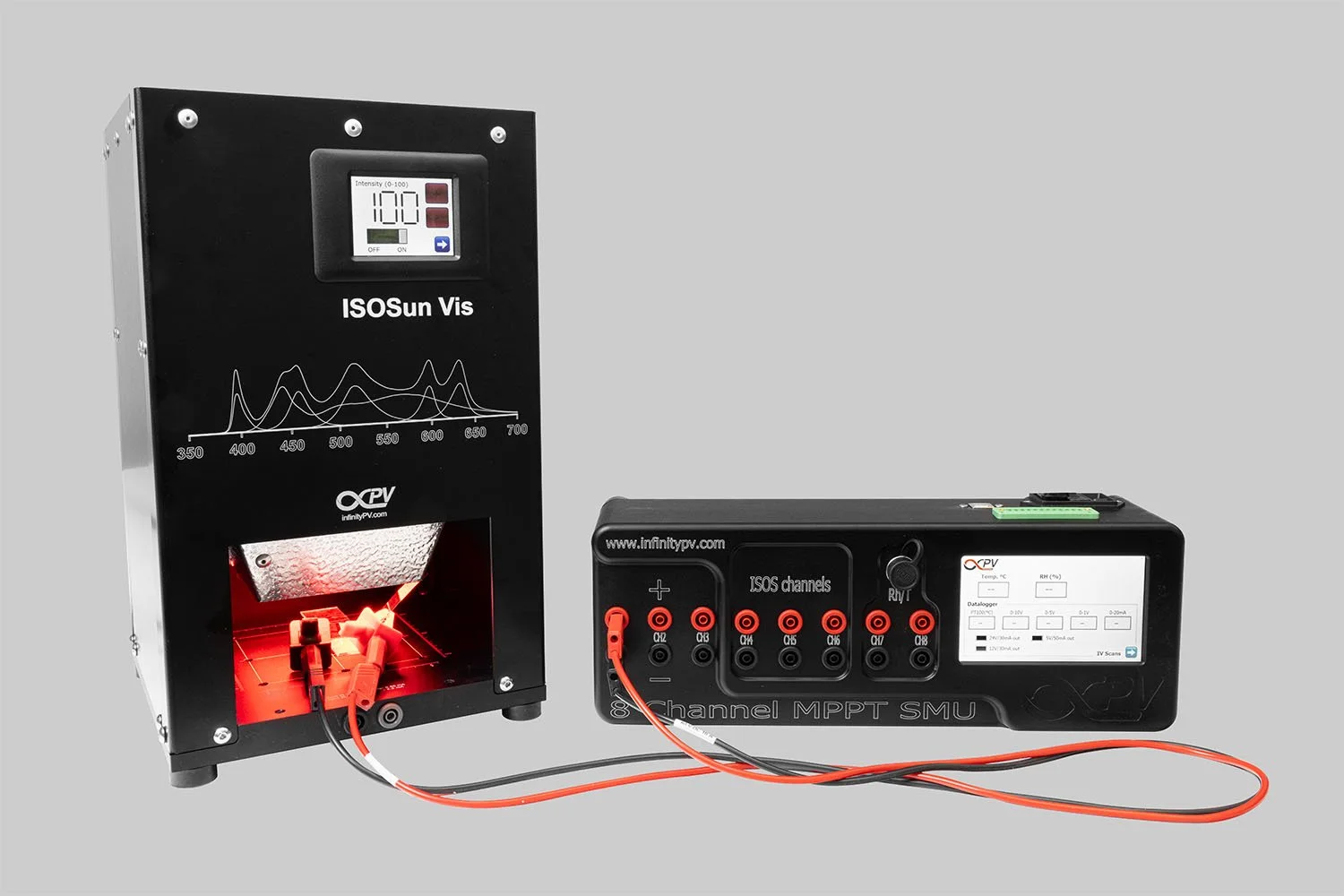
How to test solar cells using a source measure unit and solar simulator.
Get Professional Support for Your Coating Needs
Need help with slot-die coating, coating machines, or any related applications?
Contact infinityPV’s experts today for professional guidance and support.
Related Articles

Related Products

Laboratory Roll-to-Roll Coater
A compact and modular high precision roll-to-roll slot-die coater that transforms the way thin functional films are printed and coated.

Slot-die Coater
A state-of-the-art, compact sheet coater for precise, consistent slot-die coatings, featuring a vacuum chuck, integrated drying, and optimized ink delivery.
LR2RC500 Bundle
Probably the world’s most compact R2R slot-die coater. A compact, fully integrated R2R coater that fits on a workbench, in a fume hood or a glovebox.

Slot-die Heads
Slot-die heads for high-quality coatings. Available in stainless steel, titanium, or PEEK, with widths from 40 mm to 305 mm, ensuring precise thin-film production.

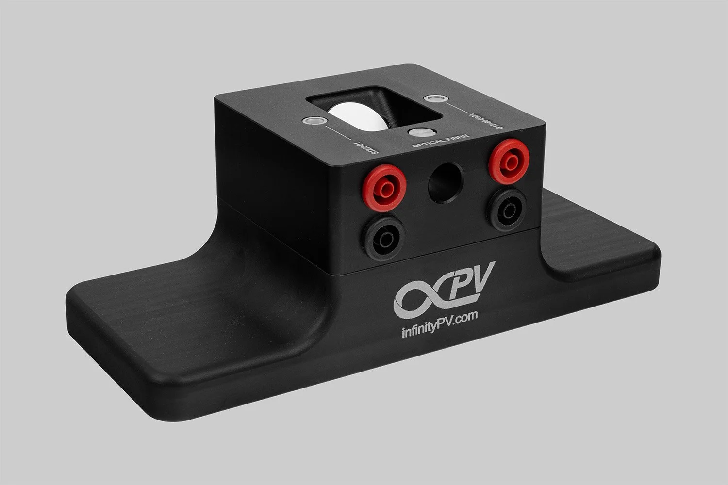


Calibrate the ISOSun Pro Max Simulator with high-accuracy triple sensors (375–2100 nm), fiber-optic connectivity, and full AM1.5G spectral control for advanced solar cell characterization and customized testing.