The Four Quadrants of Source Measure Unit (SMU) Operation Explained: Applications in Electronics and Solar Cell Testing
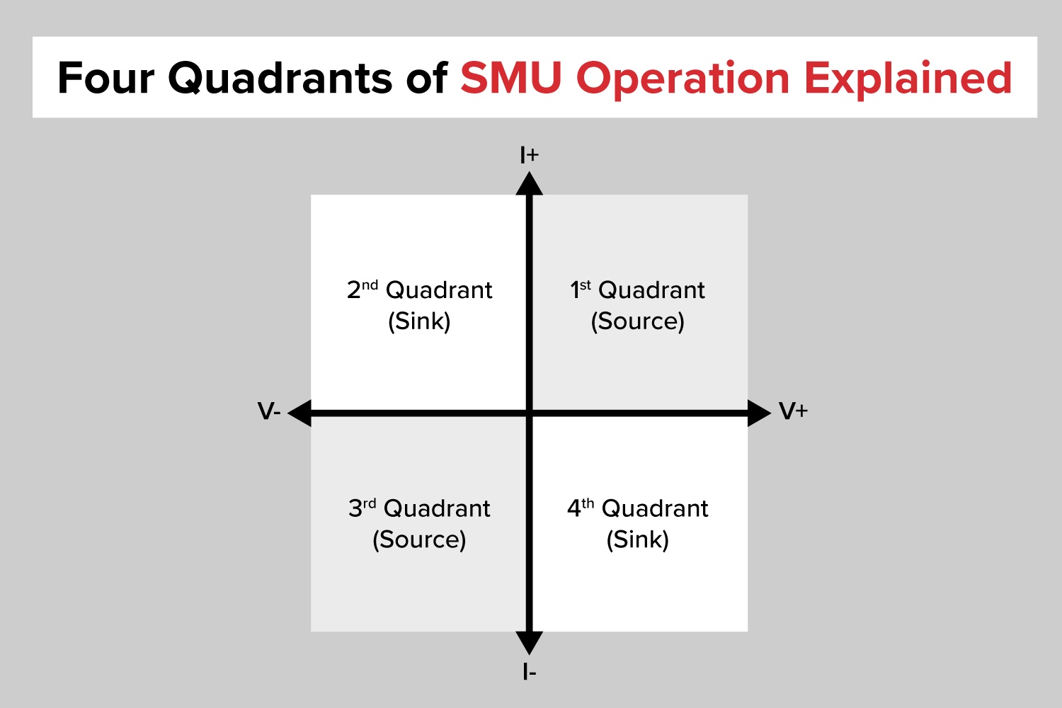
The Four Quadrants of Source Measure Unit (SMU) operation refer to the ability of the device to source and measure both voltage and current, allowing for operation in different regions of the I-V characteristics of electronic devices. Each quadrant represents a combination of sourcing and measurement capabilities:
First Quadrant (+V, +I) – Power Source
The SMU sources positive voltage and positive current.
It delivers power to a device under test (DUT).
Example: Powering an active circuit or a battery under charging conditions.
Second Quadrant (-V, +I) – Reverse Electronic Load
The SMU sources negative voltage but sinks positive current.
It absorbs power while maintaining a negative voltage.
Example: Simulating reverse bias conditions for semiconductors.
Third Quadrant (-V, -I) – Reverse Power Source
The SMU sources negative voltage and negative current.
It delivers power in reverse polarity.
Example: Testing devices with bidirectional behaviour like diodes or reverse-polarity circuits.
Forth Quadrant (+V, -I) – Electronic (active) Load/ Power Sink
The SMU sources positive voltage but sinks negative current.
It acts as an active load, absorbing power from the DUT.
Example: Discharging a battery while maintaining a controlled voltage.
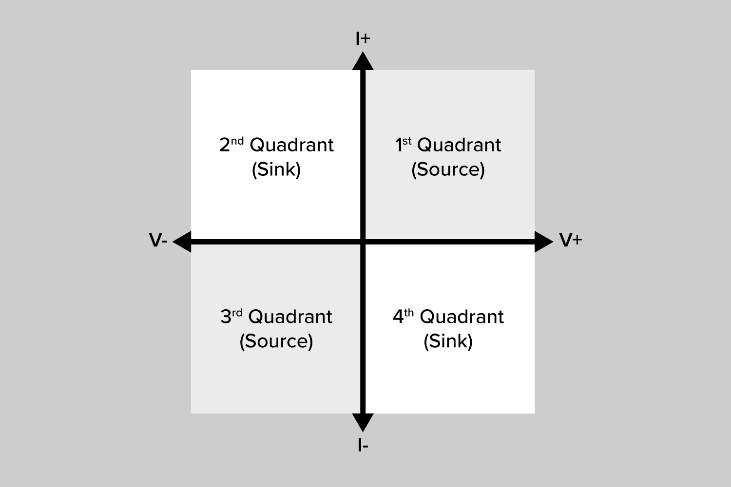
SMU Sign Convention
Please note that in this post we are using the SMU-centric convection, i.e., signs defined by what the SMU is doing. Q1& Q3 source power and Q2 & Q4 sink power.
Key Applications of Four-Quadrant Operation
Battery Testing: Charging (1st quadrant) and discharging (4th quadrant).
Semiconductor Characterization: Measuring diode I-V characteristics in both forward (1st quadrant) and reverse (3rd quadrant) bias.
Energy Harvesting Systems: Simulating power flows in both sourcing and sinking conditions.
Power Electronics: Evaluating bidirectional converters and regenerative systems.
The ability of an SMU to seamlessly transition between these quadrants makes it an essential tool for advanced electrical testing and research
How the Four Quadrants Apply to Solar Cell Testing
Fourth Quadrant:
I-V Curve Tracing under illumination: Determining efficiency, Voc, Isc, and MPP.
The SMU acts as an active load, sweeping voltage from 0V to open-circuit voltage (Voc) while measuring the current (or from Voc to 0V). This sweep crosses the 4th quadrant (+V, -I), where the solar cell generates power under illumination sourcing current back to the SMU (which sinks the generated current).
The sweep furthermore allows for determination of the short-circuit current and open-circuit voltage points at the intersections of 3rd/4th quadrants and 4th/1st quadrants, respectfully. Some protocols include a small negative-V segment (3rd quadrant) and may extend slightly Voc (1st quadrant) to full I-V map, probe reverse behaviour and observe forward-injection.
First Quadrant (V, +I) – Positive Bias with Forward Current Flow:
Full I-V map: ensuring continuous smooth sweeps through I=0 crossing.
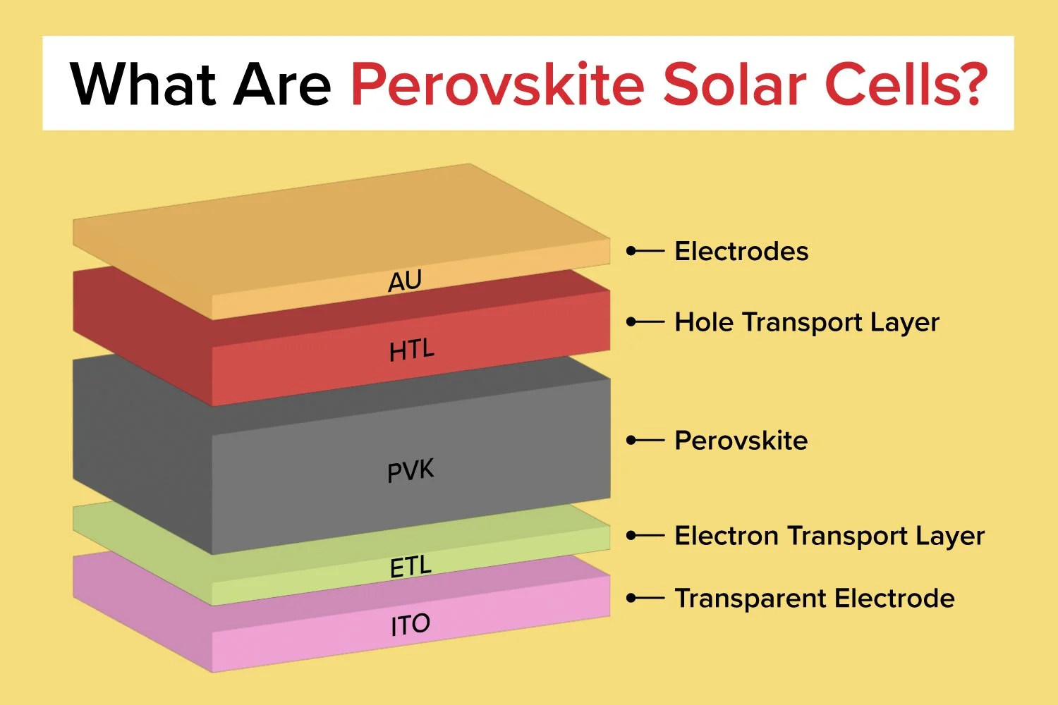
Dark I-V Testing: is a fundamental test used to analyse the electrical behaviour of a solar cell without illumination. This method helps identify defects, leakage currents, shunt resistance, series resistance, and diode ideality factors, providing insight into the intrinsic properties of the photovoltaic (PV) material.
Pre-bias the solar cell at forward bias (electrical injection) to modulate recombination, trap filling, or to “reset” the cell before measurement.
Third Quadrant (-V, -I) – Reverse Current Injection
The SMU sources negative voltage and negative current into the solar cell.
Breakdown Voltage Measurement: Important for reliability—solar cells may experience reverse bias in shaded conditions. Example: Perovskite solar cells often have low reverse breakdown, making them vulnerable.
Degradation Studies: Reverse bias can induce hot spots, shunts, or material degradation. Helps in understanding reverse-bias stability for real-world conditions (e.g., partial shading).
Tandem Solar Cells: If one subcell generates less current, the other may force it into reverse bias. Testing in the third quadrant helps identify weak subcells and reverse current handling.
Second Quadrant (-V, +I) – Negative Bias with Forward Current Flow
Hybrid or Bipolar PV devices: Certain advanced structures (Si heterojunctions with bipolar conduction, perovskite–BJT hybrids, photodetectors) can still support forward-like conduction under reverse external bias.
Post-Breakdown Recovery Studies: After a solar cell or diode experiences reverse breakdown (normally measured in Q3), some materials show self-recovery or peculiar conduction paths. Researchers sometimes apply controlled current injection (Q2) to study post-breakdown conduction or healing effects.
Illuminated Reverse Bias with External Drive: Normally, an illuminated cell at reverse bias lives in Q3 (−V, −I), because current flows from the cell into the SMU. But if you want to force a current in the opposite direction while still holding −V, the SMU enters Q2. This is used in stress/degradation testing, where you combine reverse bias with external injection to accelerate aging.
By leveraging an SMU’s four-quadrant capability, researchers can fully characterize solar cells under various conditions, improving efficiency and reliability analysis.
How to test solar cells using a source measure unit and solar simulator.
Get Professional Support for Your Coating Needs
Need help with slot-die coating, coating machines, or any related applications?
Contact infinityPV’s experts today for professional guidance and support.
Related Articles


Related Products

Laboratory Roll-to-Roll Coater
A compact and modular high precision roll-to-roll slot-die coater that transforms the way thin functional films are printed and coated.

Slot-die Coater
A state-of-the-art, compact sheet coater for precise, consistent slot-die coatings, featuring a vacuum chuck, integrated drying, and optimized ink delivery.
LR2RC500 Bundle
Probably the world’s most compact R2R slot-die coater. A compact, fully integrated R2R coater that fits on a workbench, in a fume hood or a glovebox.

Slot-die Heads
Slot-die heads for high-quality coatings. Available in stainless steel, titanium, or PEEK, with widths from 40 mm to 305 mm, ensuring precise thin-film production.

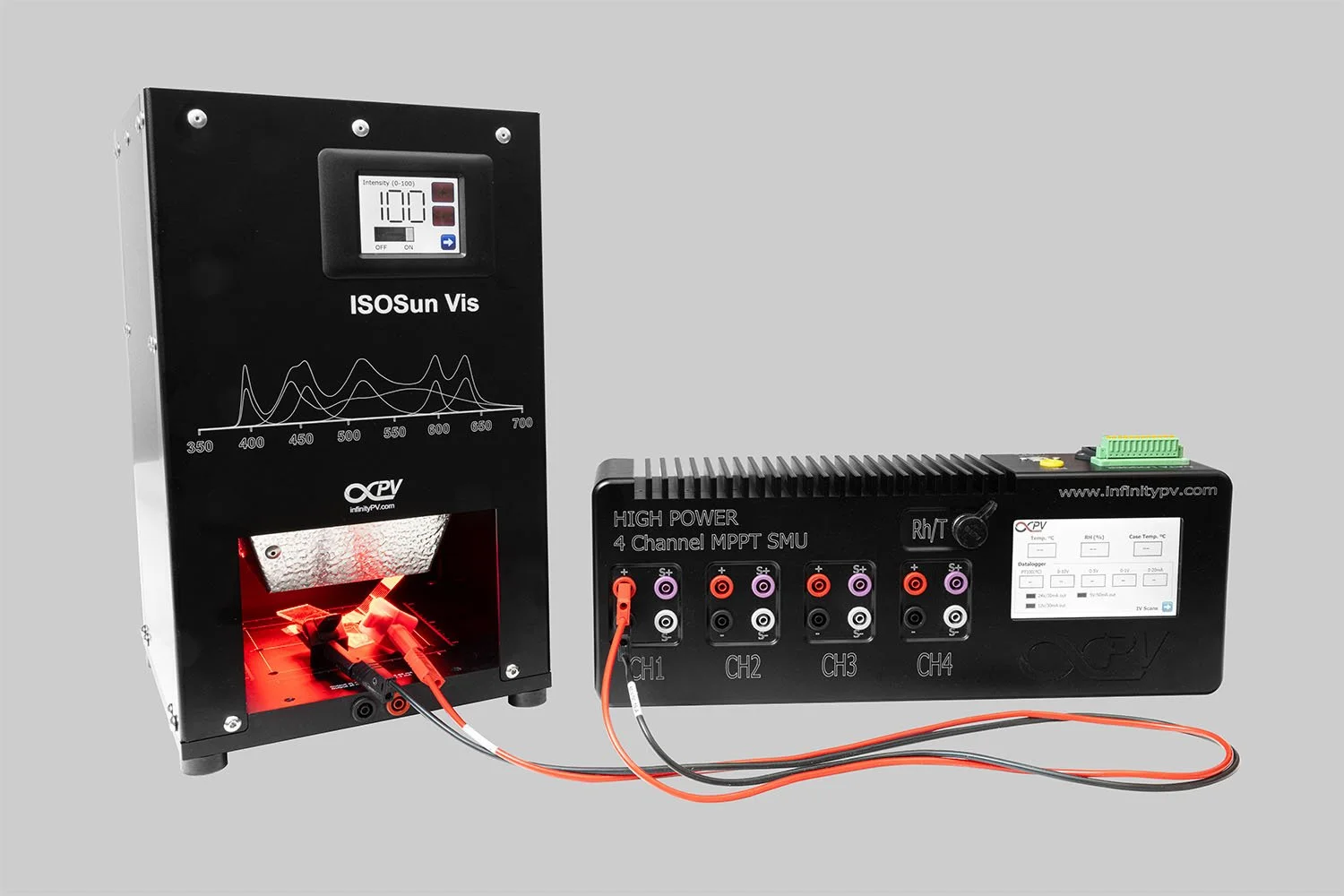
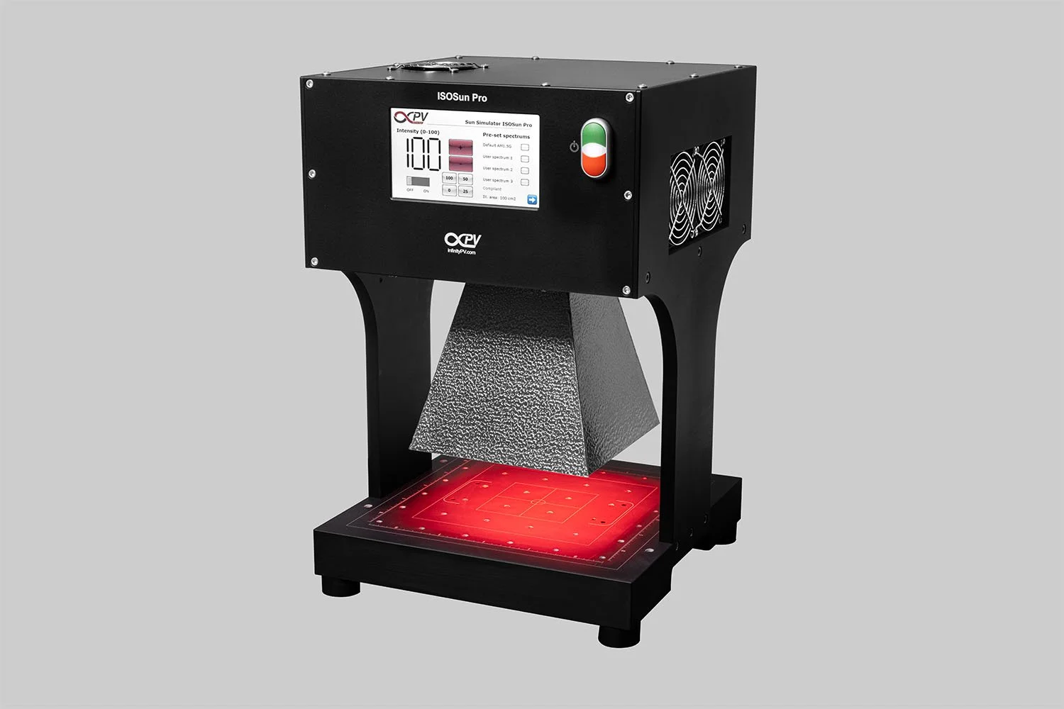


Get started with solar cell research with a complete, ready-to-use system. This bundle combines a compact Solar Simulator and an 8 Channel Source Measure Unit to make PV characterization easy and accessible.